Made with
Data Flow Diagram
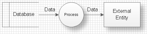
Data Flow Diagram (DFD) is the part of the SSADM method (Structured Systems Analysis and Design Methodology), intended for analysis and information systems projection. Data Flow Diagrams are intended for graphical representation of data flows in the information system and for analysis of data processing during the structural projection. By means of data flow diagrams, it is possible to show visually the work of the information system and the results of this work. Data Flow Diagram visualizes processes, data depositories, and external entities in information systems and data flow connecting these elements.
Data Flow Diagram consists of the following components:
- Processes and functions which represent actions that happened in the information system;
- External entities which represent in the system data ingoing and outgoing from it;
- Data depositories which represent places in the system where data can be saved for a definite period of time;
- Data flows, indicating the direction and character of data flowing in the considered information system.
This variant of presentation of Data Flow Diagram objects got the name of Yourdon – de Marco notation.
Objects of Data Flow Diagrams are interpreted in the following way:
- Processes transform input data flows into output data flows;
- Data depositories serve only for the keeping of ingoing data and do not change them;
- Data flows changes in external entities do not considered.
Every diagram object should have a name. Each data flow is denoted with an indication of transferred data and with the possibility of an indication of the format of these data. Data Flow Diagram should not involve more than 10 objects, excluding arrows, representing data flows. In the case of a more complicated system, the totality of several objects (as a rule, processes) is united and represented on the diagram in the form of one object. This complicated compound object is presented in the form of a separate flow diagram. Each component has a number, at this, diagrams illustrating compound objects are numerated starting from the number of an object which they describe. For example components of the diagram of the description of an object with number 5 will be enumerated 5.1, 5.2, etc. Generally, Process Flow Diagram depicts just the major equipment without details.
For clearness, there is a possibility to duplicate notations of used data depositories and external entities. Processes can't be duplicated. For example, if one the same data depository is used in several different processes it is better to duplicate it on the diagram but not to create several intricate data flow arrows from one object to several processes. This concerns external entities as well. Duplicates of data depositories are marked with the double line from the left side, external entities duplicates - with the asterisk.
Data flow on the diagram can ramify and merge which implies branching or confluence of data in the information system.

Example 1. Data Flow Diagram
Thus the information system is represented by a planner in the form of the high-level DFD in which objects are worked out in detail by diagrams of the lower level with the preset level of detailed elaboration. There is also another way of looking at which all events in the system are described at once and each event is represented in the form of process transforming data flows, further these sub runs are grouped for getting diagrams of the higher level.

Example 2. Data Flow Diagram in ConceptDraw DIAGRAM
The following features make ConceptDraw DIAGRAM extended with Data Flow Diagrams Solution the best Data Flow Diagram software:
- You don't need to be an artist to draw professional-looking diagrams in a few minutes.
- Large quantity of ready-to-use vector objects makes your drawing diagrams quick and easy.
- A great number of predesigned templates and samples give you a good start for your own workflow diagram or process flow diagram.
- ConceptDraw DIAGRAM provides you the possibility to use the grid, rules, and guides. You can easily rotate, group, align, arrange the objects, use different fonts and colors to make your organizational workflow diagram exceptionally looking.
- All ConceptDraw DIAGRAM documents are vector graphic files and are available for reviewing, modifying, and converting to a variety of formats: image, HTML, PDF file, MS PowerPoint Presentation, Adobe Flash, MS Visio.
- Using ConceptDraw STORE you can navigate through ConceptDraw Solution Park, managing downloads and updates. You can access libraries, templates, and samples directly from the ConceptDraw STORE.
- If you have any questions, our free of charge support is always ready to come to your aid.
TEN RELATED HOW TO's:
Diagram of a Basic Computer Network. Computer Network Diagram Example →
What is a computer network? This is a set of devices and systems that are connected to each other (logically or physically) and communicate with each other. This could include servers, computers, phones, routers, and so on. The size of this network can reach the size of the Internet, and can consist of only two devices connected by a cable. This sample shows the connection scheme of the home WLAN equipment to the Internet. 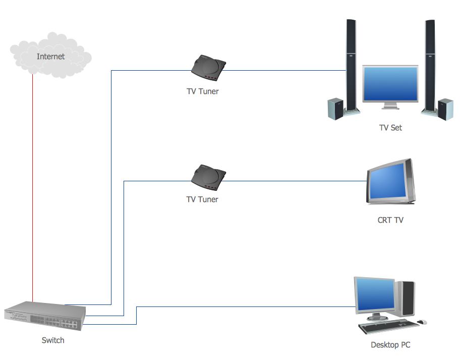
Picture: Diagram of a Basic Computer Network. Computer Network Diagram Example
Related Solution:
Flowchart Programming Project. Flowchart Examples →
Flowcharts can be used in designing and documenting both simple and complex processes or programs and, similar to the other types of diagrams, they can help visualize what happens and so help understand some definite process, and, as a result, find flaws, bottlenecks and other features within it. 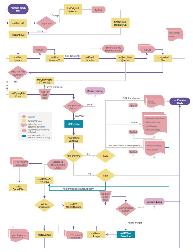
Picture: Flowchart Programming Project. Flowchart Examples
Related Solution:
How to Draw a Flowchart →
Data processing can be very complex sometimes. If you are interested in facilitating your work with data, it's time to learn how to draw flowcharts with special software or using just a piece of paper. The list of flowchart basic symbols includes rectangles, diamond, ellipses etc. and is used to represent processes, actions, decisions or data processing. A well-done flowchart bring the clearness of the sequence of a process stages. There are number of symbols that can be used in flow charts to show various sorts of steps. The basic flowchart can be created using a few of them: Process, Decision, Start/Finish. A basic element of a flowchart represents a simple action and looks like a box, that contains a description of the action. The depicting of actions sequence is made with arrows between corresponding action boxes, as you can see on the sample diagram. Also it shows the symbols for flowchart start and finish steps. ConceptDraw Flowcharts solution provides the ability to build basic flow charts as well as the ones of any size and complexity with a minimum of actions. 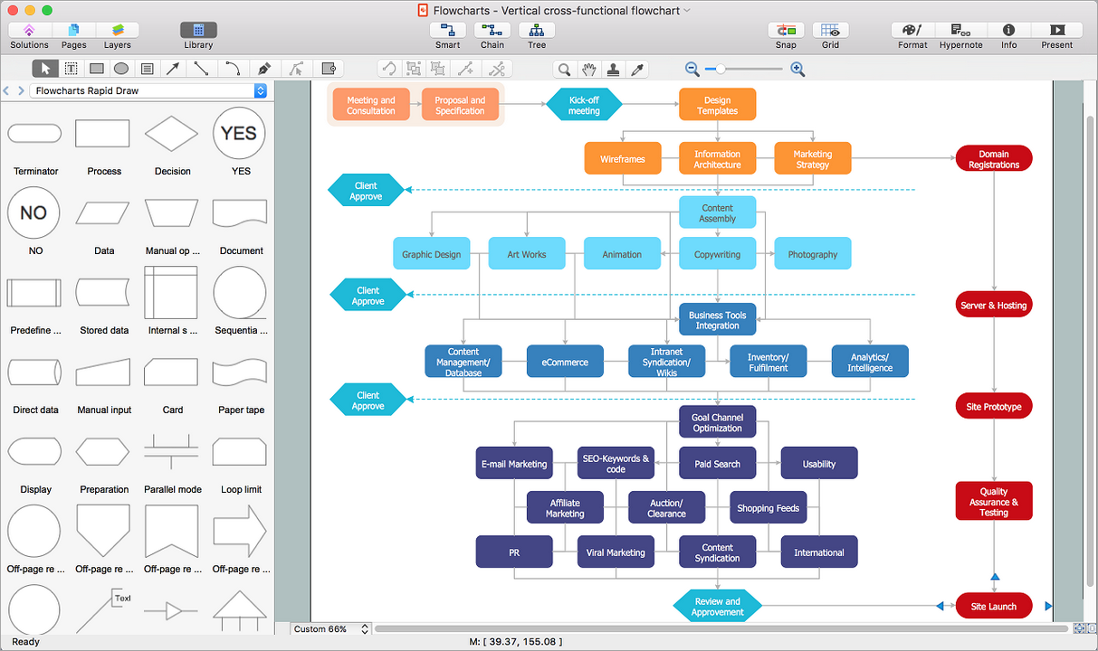
Picture: How to Draw a Flowchart
Related Solution:
Database Design →
ConceptDraw DIAGRAM extended with IDEF Business Process Diagrams solution from the Business Processes area of ConceptDraw Solution Park is an ideal software for effective database design and drawing IDEF diagrams visually representing all steps of database design process. 
Picture: Database Design
Related Solution:
Easy Flowchart Program and Standard Flowchart Symbols →
Fast visualization of structured data is main capability of the ConceptDraw DIAGRAM. With numerous vector stencils and standard flowchart symbols from object libraries and the RapidDraw technology this program stands as the best professional flowchart software for drawing with type of flowchart symbols. ConceptDraw DIAGRAM also known as best flowchart maker. 
Picture: Easy Flowchart Program and Standard Flowchart Symbols
Related Solution:
IDEF0 Diagram →
The vector stencils library IDEF0 Diagram from the solution IDEF0 Diagrams contains specific IDEF0 diagram symbols such as arrow symbols and entity symbols for ConceptDraw DIAGRAM diagramming and vector drawing software. The IDEF0 Diagram solution is contained in the Software Development area of ConceptDraw Solution Park. 
Picture: IDEF0 Diagram
Related Solution:
Electrical Drawing Software and Electrical Symbols →
No building project can exist without an electrical circuit map. It's more convenient to develop electrical drawing with a proper software which would contain vector shapes and electrical symbols. This will help in the future if any problems appear. This circuit diagram shows the scheme of a location of components and connections of the electrical circuit using a set of standard symbols. It can be use for graphical documentation of an electrical circuit components. There are many of different electric circuit symbols that can be used in a circuit diagram. Knowing how to read circuit diagrams is a useful skill not only for professionals, but for any person who can start creating his own small home electronic projects. 
Picture: Electrical Drawing Software and Electrical Symbols
Related Solution:
Source: https://www.conceptdraw.com/How-To-Guide/data-flow-diagram
Posted by: marionmarioneyakelea0252217.blogspot.com
